Friday, September 7, 2012

Little update on the FPV backpack

I added dip switches for both TX and RX modules to change operating channels, also i made the transmitter base bit better. But the most important thing i did is that i made some better quality ( comparing to my first ones) cloverleaf and skew planar antennas.


They say that these antennas work best on the 5.8 ghz band because of the frequency characteristics, and you certainly can feel the difference. Video link was solid , thus i did not fly too far because im still not comfortable to fly only with the live video. Anyway, if you have a 5,8 ghz tx rx system, i suggest you to make these antennas, your first or second attempt may not work as good ( fourth attempt for me till i managed to make them look good) so don't give up if it does not fulfill your expectations

Saturday, August 25, 2012

Wednesday, August 22, 2012

FPV backpack. The early build

Today i got the RX5808 and TX5823 modules in my mailbox and i started working on them right away. I ordered these from foxtechfpv. Bruce from RCModelReviews said that there are other suppliers that you can buy these modules from cheaper than 15 and 20 dollars , but i was really waiting for it 6 months and the tutorials, part lists and PCB's never came, i learned how to make PCB's and build and use RF circuits for this purpose.

I have these connected with just a little wires as antennas. I will write about these too, because i made a mistake soldering these on.


For right now i only have this big TV for testing purposes, it way too big to carry outside for FPV flying.


I had these only for a day but i already have some tips for you. The little metal pieces which you connect the wires , you have to be really careful, when i soldered on the 1mm copper wire pre-cut for exact frequency i ended up ruining the transmitter module RF output piece, now the bottom part of the pcb i have nowhere to solder on the antenna, there is just a little metal piece left on the top of the module, i hope you understood what i tried to point out, so just be careful, i say when you are testing it don't connect any thick wires to it, just very thin copper wires, the little wires that came with the modules as antennas broke off the TX'es rf output part all along, if you have access to the SMA connectors you should get them, its worth it


For the RX module i used the 7805 with few capacitors to get the right voltage for the module  so i don't make the magic smoke come out, for the video output i used a barrel connector, for the RF in i still have the bad 1mm wire for it which could ruin the joint too, i have to take it off...
Also i put a little connector to make it more easy to use , disconnect.


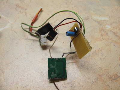
For the transmitter, right now i have it just in testing stage, i already designed PCB prints for both TX and RX, if they will work, i will post the images here. As i said i want a pcb before i ruin it and i need to buy another one. For the input voltage i went to the local shop and they gave me some 3.3volt regulator, i found out which pin is for what, added capacitors in both input and output, then i connected the input pins to two cells of my three cell lipo battery. As i said now its only in test stage, i have it on two cells so i don't have to make the little regulator to put up with a lot of work and make it too hot and probably burn it. My UBEC from hobbyking still haven't arrived so i have to do that.  A JR servo extension is used for video input and camera power supply wires. White wire goes into the video pin of the TX ,  camera ground goes to the ground of the tx or else it wont work. Ground and positive leads of the extension cable are connected to the balance port of the lipo battery.


I got my camera from  http://www.securitycamera2000.com/products/420-TVL-3.6mm-Lens-Color-CMOS-Board-Camera-for-CCTV-Security.html and i noticed that it has a 7805 on it, so i found that it can work quite happily from a two cell battery.

So if nothing changes ill build the PCB's and i will keep you updated

Monday, August 6, 2012

Homemade 5.8 GHz FPV System - Bill of materials

I have been watching RCModelReviews videos for a long time and he made few videos about showing how the system works and recently he started uploading videos on how to make each part of the backpack and now since the summer is about to end and i have no project on my hands im considering buying the components and making one system myself. Here i will post my bill of materials for all the needed parts and shipping and whatnot.

 TX5823 - 20 dollars http://www.foxtechfpv.com/tx5823-200mw-8ch-58g-tx-module-for-nano-flyers-p-272.html 

RX5808 - 15 dollars http://www.foxtechfpv.com/rx5808-58g-8ch-receiver-module-p-303.html 

Foxtechfpv shipping - 6.50 dollars

Hobbyking shipping - 4 dollars

 A Cheapo CCD camera from hobbyking - 17 dollars http://www.hobbyking.com/hobbyking/store/uh_viewItem.asp?idProduct=11977

 UBEC - 4 dollars http://www.hobbyking.com/hobbyking/store/uh_viewItem.asp?idProduct=15212 

DIP Switches -  0.5 dollars (local shop)

3.3v regulator - about 0.4 (local shop)

The Modules will arive any day this week, i will keep you updated

Sunday, July 29, 2012

Veronica 1W FM Transmitter


I Made the transmitter about a month ago and im not using it as much these days, so i will write about it after the month of building and using. I chose to build this transmitter mainly because that there were alot of discusuions about it in forums  and that the circuit for this transmitter had a PCB image attached to it  really was easy not to screw something up when desiging your own pcb design. The very first time i made this board it turned out mirrored. Because i was inexperienced i desided to start all over and get it right.

Before building it i had to find all the substitute parts for the circuit because half of the parts used on the original one doesnt seem to exist anymore.
Instead of the BC548 transistors i used BC547 . Instead of the BF494 i used BF199.  Instead of the power transistor 2N4427 i used a 2N3866.  I substituted the D1 double varicap KV1310 with a BB204  and everything is working. Sucess! Very first times i turned it on i tought it wasnt working because the LED just wouldnt work. It turned out that i was using too low voltage to make the tuning easy. On 12 volts 1 amp the LED just wouldnt light up strong enought for me to notice that im tuning. Next time i gave it 13-14 volts and you could really see the LED glowing bright, then i could tune it properly to a desired frequency. All the coils were made from 1mm copper wire formed on the required size drill bits . When touching anything it  frequency remains stable . The range i got from it wasnt very amazing, but i wasnt even pulling a watt, you need about 15 16 volts for that.

Making this cost me about 50 Litas (~15 euro) . Building it was great fun . Power transistor, varicap and BF199's had to be ordered in my local shop. The power transistor came all the way from germany!
If you do find yourself making one of these and you come across some trouble feel free to ask me here i will be happy to help you with it. I was pretty lost when i had to pick the right substitutes but here , i did it. I had it on without any antenna on 12 volts several times and the thing didint burnout or exploded. People said to me that this circuit is over-complex  and has way too much parts for such a homemade device. They might be right but when i looked for a circuit to make i found none that had a pcb image ready for me to print and make. An RF amplifier for this would be nice!

Saturday, July 28, 2012

F-22 Scratch built Rc plane

Few days ago i made this plane : http://www.rcgroups.com/forums/showthread.php?t=740049
And here is what i got. The construction of the thing is dead simple. Before i got the thing into the air i crashed it several times because the cg was way off. This is the 24 inch version. My friend made the bigger one and the cg was somewhere by the motor mount, on this one turns out it had to be much further to the nose.
 I used a 30amp ESC , a hextronik 3000kv 24 gram  motor , 6x4 prop , 1000mah 2 cell battery, HXT 9 gram servos. This kind of setup is way too weak for such a plane. To make it stay in the air i have to give more than half throttle. I guess the battery should be 3 cell or the motor kv is bit too high .  I bought every single part from hobbyking by the way.


When in the air i cant do any kind of acrobatics with such a weak thrust, also the thing is loud as hell, all the dogs start to bark around the neighbourhood when give it full throttle.


All in all its not a keeper for me with such rc gear i have for a plane right now, but it is fun to fly, it looks really awesome when passing by your head.


Wednesday, July 25, 2012

Bangkok, Thailand meteo radio on 8743khz

Caught this in  2012 07 19 2000z accidentally scanning around with the long wire connected

Thursday, July 19, 2012

Useful radio and transmitters related links

While gathering info on how to make transmitters i stumbled upon all kinds of websites about radio with allot of useful information.

http://www.hfunderpants.com/
http://priyom.org/
http://www.udxf.nl/
http://www.hfunderground.com
http://freeradiotx.blogspot.com/
http://www.sm7ucz.se/KRAS/KRAS.htm
http://danyk.wz.cz
http://ebookbrowse.com/7mhz-cw-am-qrp-transmitter-2-pdf-d155417007
http://www.qrz.lt/ly2bok/Konstrukcijos/Konstr%20turinys.htm
http://kd1jv.qrpradio.com/
http://www.gameangler.eu/delboy/m0dad/main_page.htm
http://www.elektronika.ba/schematics/
http://www.vhfdx.info
http://www.talkingelectronics.com/te_interactive_index.html


Pixie 2 CW QRP Transmitter

I have tried making the Pixie 2 QRP transmitter on a perfboard and it didint work , i designed my own pcb for it and it didint work. Maybe it had something to do with me using BC547 as the two transistors required in the schematic or i could just have made a mistake in the design. Because i had all the parts for Pixie 2 laying around i googled around and found this nice website http://www.circuitswamp.org/projects/pixie2.html   . It has a very nice pcb design and clear instructions, so i made it with BC547 as Q2 and  for Q1 i used a random RF transistor i salvaged from somewhere, for the L2 i wound 8 turns around a FT50 ferrite ring . My pcb turned out mirrored (my mistake) so i had to bend the legs of the LM386 chip all the way to make it work on a mirrored pcb.
And it works! I have no idea what is the output power on this thing. And when listening on headphones you cant hear a single signal. I read that pixie 2 receiver is deaf, but it could be that there is not much activity on 3578khz (crystal freq) . If you want to know how it works read the text in circuitswamp.org link i gave  because im not an expert on these things. Wonder if its possible to make a contact with this thing here where i live.

Wednesday, July 18, 2012

Hello

Hello my name is Linas. I live in Lithuania. I have alot of hobbies and i thought that making a blog to keep track of things that i make, made and want to make creating a blog would be a great idea. I love listening to shortwave radio, i like fishing, cycling, making pcb's and electronics in general, pyrotechnics , flying radio controlled airplanes also making them, photography. Recently i got interested  about making all sorts of transmitters, still low power. When i think about it i cant name all of all the hobbies i have and things i like.

Have a complimentary bird