Friday, December 27, 2013

Kenwood TS820S cathode resistor repair


Some time ago after pushing the rig too far with an antenna that was out of tune i killed both original cathode resistors in the final unit of my Kenwood.As you can see in the picture they both are cracked and when squeezing them the resistance changes significantly. I had no other option than to replace them. I used two 1 watt 10 ohm resistors from my local shop.


But after what i would call a normal operation these both resistors bursted in fire. Maybe i didint check the SWR of the antenna at that point or maybe these Chinese resistors are bad quality.I will try to put the same type new ones and try to work come contacts and see if they will do that again, because putting in a bigger, higher wattage resistors would mean that the rig would lose some of its protection in the final amp section that these resistors originaly provided.


Tuesday, July 2, 2013

Images from the space : ISS SSTV

Today i stumbled upon some SSTV signals on the ISS frequency 145.800. I couldn't record the other one i heard because i couldn't find my phone in time. I just managed to catch this. Sorry for the bad image quality, the only antenna i had up is a 6 el yagi for vhf, i needed to track the satellite manually in order to not loose the signal completely. 
This was heard on July 2 , around 11.11 UTC in Lithuania.

Monday, June 24, 2013

Fixing a Kenwood TK-709 VHF mobile radio

I got this transceiver from a local ham radio operator LY3PEJ as a gift. It took me a couple of days to fully understand it and make it work as everything should. It came with only a few frequency presets that i did not really need. I borrowed the programming cable but for some reason it didint work. Now i know that there were a couple of problems both on the computer the programing software was and the transceiver.

After alot of investigating and trying to find info i found that on the face panel by the microphone jack (you need to disasemble the radio for that) there is a small SMD fuse marked 20 . I tested that with the multimeter and it was shot, thus not delivering 12v into the programing cable. Besides that, for some reason the microphone ground connection was a little burned too, so i just connected that with a wire to the main ground.  In order to fix the fuse, i took a very fine copper wire and soldered it on the fuse contacts.
If you are making the cable, this one works just fine http://highfields-arc.co.uk/constructors/other/kpg4.htm . In order to program the radio i had to use an old pc which has a RS232 port. It can be done using a USB to RS232, for the information how to run the KPG-20D software  in DOSBOX read this page http://www.george-smart.co.uk/wiki/Kenwood_PMRs

Friday, September 7, 2012

Little update on the FPV backpack

I added dip switches for both TX and RX modules to change operating channels, also i made the transmitter base bit better. But the most important thing i did is that i made some better quality ( comparing to my first ones) cloverleaf and skew planar antennas.


They say that these antennas work best on the 5.8 ghz band because of the frequency characteristics, and you certainly can feel the difference. Video link was solid , thus i did not fly too far because im still not comfortable to fly only with the live video. Anyway, if you have a 5,8 ghz tx rx system, i suggest you to make these antennas, your first or second attempt may not work as good ( fourth attempt for me till i managed to make them look good) so don't give up if it does not fulfill your expectations

Saturday, August 25, 2012

Wednesday, August 22, 2012

FPV backpack. The early build

Today i got the RX5808 and TX5823 modules in my mailbox and i started working on them right away. I ordered these from foxtechfpv. Bruce from RCModelReviews said that there are other suppliers that you can buy these modules from cheaper than 15 and 20 dollars , but i was really waiting for it 6 months and the tutorials, part lists and PCB's never came, i learned how to make PCB's and build and use RF circuits for this purpose.

I have these connected with just a little wires as antennas. I will write about these too, because i made a mistake soldering these on.


For right now i only have this big TV for testing purposes, it way too big to carry outside for FPV flying.


I had these only for a day but i already have some tips for you. The little metal pieces which you connect the wires , you have to be really careful, when i soldered on the 1mm copper wire pre-cut for exact frequency i ended up ruining the transmitter module RF output piece, now the bottom part of the pcb i have nowhere to solder on the antenna, there is just a little metal piece left on the top of the module, i hope you understood what i tried to point out, so just be careful, i say when you are testing it don't connect any thick wires to it, just very thin copper wires, the little wires that came with the modules as antennas broke off the TX'es rf output part all along, if you have access to the SMA connectors you should get them, its worth it


For the RX module i used the 7805 with few capacitors to get the right voltage for the module  so i don't make the magic smoke come out, for the video output i used a barrel connector, for the RF in i still have the bad 1mm wire for it which could ruin the joint too, i have to take it off...
Also i put a little connector to make it more easy to use , disconnect.
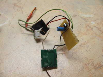


For the transmitter, right now i have it just in testing stage, i already designed PCB prints for both TX and RX, if they will work, i will post the images here. As i said i want a pcb before i ruin it and i need to buy another one. For the input voltage i went to the local shop and they gave me some 3.3volt regulator, i found out which pin is for what, added capacitors in both input and output, then i connected the input pins to two cells of my three cell lipo battery. As i said now its only in test stage, i have it on two cells so i don't have to make the little regulator to put up with a lot of work and make it too hot and probably burn it. My UBEC from hobbyking still haven't arrived so i have to do that.  A JR servo extension is used for video input and camera power supply wires. White wire goes into the video pin of the TX ,  camera ground goes to the ground of the tx or else it wont work. Ground and positive leads of the extension cable are connected to the balance port of the lipo battery.


I got my camera from  http://www.securitycamera2000.com/products/420-TVL-3.6mm-Lens-Color-CMOS-Board-Camera-for-CCTV-Security.html and i noticed that it has a 7805 on it, so i found that it can work quite happily from a two cell battery.

So if nothing changes ill build the PCB's and i will keep you updated

Monday, August 6, 2012

Homemade 5.8 GHz FPV System - Bill of materials

I have been watching RCModelReviews videos for a long time and he made few videos about showing how the system works and recently he started uploading videos on how to make each part of the backpack and now since the summer is about to end and i have no project on my hands im considering buying the components and making one system myself. Here i will post my bill of materials for all the needed parts and shipping and whatnot.

 TX5823 - 20 dollars http://www.foxtechfpv.com/tx5823-200mw-8ch-58g-tx-module-for-nano-flyers-p-272.html 

RX5808 - 15 dollars http://www.foxtechfpv.com/rx5808-58g-8ch-receiver-module-p-303.html 

Foxtechfpv shipping - 6.50 dollars

Hobbyking shipping - 4 dollars

 A Cheapo CCD camera from hobbyking - 17 dollars http://www.hobbyking.com/hobbyking/store/uh_viewItem.asp?idProduct=11977

 UBEC - 4 dollars http://www.hobbyking.com/hobbyking/store/uh_viewItem.asp?idProduct=15212 

DIP Switches -  0.5 dollars (local shop)

3.3v regulator - about 0.4 (local shop)

The Modules will arive any day this week, i will keep you updated