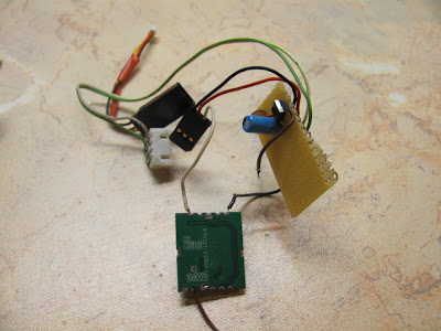
I have these connected with just a little wires as antennas. I will write about these too, because i made a mistake soldering these on.

For right now i only have this big TV for testing purposes, it way too big to carry outside for FPV flying.
 I had these only for a day but i already have some tips for you. The little metal pieces which you connect the wires , you have to be really careful, when i soldered on the 1mm copper wire pre-cut for exact frequency i ended up ruining the transmitter module RF output piece, now the bottom part of the pcb i have nowhere to solder on the antenna, there is just a little metal piece left on the top of the module, i hope you understood what i tried to point out, so just be careful, i say when you are testing it don't connect any thick wires to it, just very thin copper wires, the little wires that came with the modules as antennas broke off the TX'es rf output part all along, if you have access to the SMA connectors you should get them, its worth it
For the RX module i used the 7805 with few capacitors to get the right voltage for the module so i don't make the magic smoke come out, for the video output i used a barrel connector, for the RF in i still have the bad 1mm wire for it which could ruin the joint too, i have to take it off...
 Also i put a little connector to make it more easy to use , disconnect.
For the transmitter, right now i have it just in testing stage, i already designed PCB prints for both TX and RX, if they will work, i will post the images here. As i said i want a pcb before i ruin it and i need to buy another one. For the input voltage i went to the local shop and they gave me some 3.3volt regulator, i found out which pin is for what, added capacitors in both input and output, then i connected the input pins to two cells of my three cell lipo battery. As i said now its only in test stage, i have it on two cells so i don't have to make the little regulator to put up with a lot of work and make it too hot and probably burn it. My UBEC from hobbyking still haven't arrived so i have to do that. A JR servo extension is used for video input and camera power supply wires. White wire goes into the video pin of the TX , camera ground goes to the ground of the tx or else it wont work. Ground and positive leads of the extension cable are connected to the balance port of the lipo battery.
I got my camera from http://www.securitycamera2000.com/products/420-TVL-3.6mm-Lens-Color-CMOS-Board-Camera-for-CCTV-Security.html and i noticed that it has a 7805 on it, so i found that it can work quite happily from a two cell battery.
So if nothing changes ill build the PCB's and i will keep you updated
Hi,
ReplyDeleteI have the TX5823 and want to build an antenna similar to yours. What length is your antenna?
Thanks,
Neil